Undergraduate team
UCI Rocket Project
Student engineering team at UC Irvine that designs, builds, and flies methalox bipropellant liquid rockets and solid rockets. rocket.eng.uci.edu
Propulsion Engineer
PTR VTF and launch · 2022–2023
Lead Propulsion
MOCH4 redesign · feed, tanks, injector
Chief Engineer
Test Director · 30+ cold flows, 3 hot fires
Propulsion Engineer
2022–2023 · Preliminary Test Rocket
Cryogenics
Fluids
LN2 dewar operator for PTR. I pre-chilled tanks and lines so we could load methane and LOX without boiling off the fill.Test operations
Test ops
Designed and component-tested the vent-valve actuation system, and ran the main-valve actuation system through freeze concerns before we trusted it on the stand.Cold flow
Fluids
Ran full-system cold flows to prove the feed path, fill, and venting, and to verify tank and injector pressures before we put fire on the engine.ConOps
Test ops
Concept of operations: how a system is meant to be run, including roles, sequence, modes, and decision points.
During my first year on the project I spent time understanding rocketry as a whole, primarily through keeping documentation for the propulsion team and getting hands-on experience through component and full-system testing. I also had a large role in our first Vertical Test Fire (VTF) and launch of PTR.
- Designed and component-tested the vent valve actuation system
- Tested the main valve actuation system amid freezing concerns
- Conducted full system cold flows
- LN2 dewar operator — tank pre-chill to limit propellant boil-off
- Test stand crew for PTR hot fire
- Created and refined new tank fill procedures to reduce fill time, resulting in a higher fill percentage per tank and longer fire duration
Deep divePTR hot fire and launchOpenClose
January 2023 · Test stand
Hot fire
I served on the test stand for PTR’s Vertical Test Fire. I was the liquid nitrogen dewar operator, in charge of chilling the tanks and lines so they were ready for propellant. I also owned fill troubleshooting: running the vehicle’s bleed spouts to dump backpressure, and readying the rest of the stand for the hot fire.
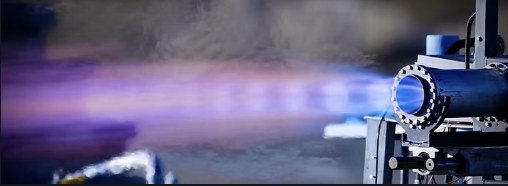
The hot fire ran clean. A little over 7 seconds of steady-state thrust at about 850 lbf.
- ~850 lbf
- Thrust
- ~7 s
- Burn duration
April 2023 · Pad
Launch
In VTF data review, the team and I saw that our fire duration was much shorter than we had planned. I figured we did not have enough propellant in the tank to hit our 15-second target. So I refined the filling procedure and the GSE hardware: I pulled a regulator off the ground system so we could fill each tank in under 10 minutes, with a reliable chill and fill procedure that held propellant temperature and fill percentage within our ideal bounds.
I was tasked with mixing the ignitor and ran flight-specific tests so PTR could be ready for flight. Three months after VTF we launched PTR, where I served as the LN2 dewar operator and ignition specialist.
PTR hit 9,100 feet with about 900 lbf on a 14-second burn. The propulsion system met its success criteria; recovery of the vehicle failed. The main came out at apogee, the recovery section tore off the rest of the vehicle, leaving PTR to disassemble and impact the ground at high speeds.
- ~900 lbf
- Thrust
- 14 s
- Burn duration
- 9,100 ft
- Apogee
Lead Propulsion Engineer
2023–2024 · MOCH4 redesign
Leadership
People
Owned the propulsion redesign for MOCH4 as Lead Propulsion Engineer.Fluid systems
Fluids
Cut PTR’s heavy feed path to one dome-loaded regulator and two normally-open remote vents so fill and fire were simpler and lighter.Structures
CAD / hardware
Designed tanks that carry flight loads and form the vehicle wall, then proofed them after a weld failed on the stand.Injector
CAD / hardware
Led the path toward an aluminum like-impinging triplet: methane–oxygen–methane.Test operations
Test ops
Headed component-level testing on MOCH4 hardware before it went on the vehicle.
After PTR, I owned the entirety of the team’s propulsion system. I headed the effort to design, build, and integrate a new system for a new rocket I named MOCH4
It is pronounced MOCHA. Our propellant choice is liquid methane (CH4) and liquid oxygen. We have a like-impinging injector that goes methane–oxygen–methane, so if you write that down you get M(ethane) O(xygen) CH4. Coffee, the propellants, and the injector choice in one name. I thought I was being clever. I still do.
- Redesigned the feed system to be lighter, more efficient, and have simpler ConOps
- Cut the feed path to one dome-loaded regulator and added two normally-open remote vent valves
- Led injector redesign to test a path toward an aluminum triplet impinging injector
- Integrated structural tanks
- Headed component-level testing on all hardware for MOCH4
Deep diveFeed system, tanks, and P&IDOpenClose
Mass, area, parts
Feed system
The PTR’s feed system was carrying too much weight, had an excessive cross-sectional area, and included too many components. MOCH4 needed to generate more thrust, be lighter, experience less drag, and operate more cleanly. The feed system was the main culprit in these issues, affecting every other part of the rocket.
I implemented a design change to feed both propellant tanks from a single dome-loaded pressure regulator, which balanced their pressures and flow rates into the injector. Additionally, I swapped out PTR’s two manual vents and two solenoid vents for two normally-open, cryo-rated remote vent valves. This overhaul reduced the feed system’s weight by over 50 pounds. Cold-flow operations decreased from approximately 6 hours to about 2, and tank filling became nearly hands-free, requiring only the opening of the dewars.
- 50+ lb
- Feed mass saved
- 6 h → 2 h
- Cold-flow ops
Structural
Tanks
PTR initially used two separate tanks beneath the skin, which only carried propellant and offered minimal additional support. For MOCH4, I designed structural tanks that match the rocket’s outer diameter to handle flight loads. I led the team responsible for their design, testing, and integration. After receiving them from the shop, I inspected them, and a weld failure was discovered. We caught it during testing and repaired it before integrating the tanks into MOCH4’s system.
Chief Engineer & Test Director
2024–2025 · Hot-fire campaign
Leadership
People
Chief Engineer on MOCH4. I owned the project’s technical direction once the new propulsion system was on the vehicle.Test operations
Test ops
Test Director for 30+ cold flows and 3 vertical test fires. I rebuilt procedures, crew roles, and count so cold flow and hot fire used the same ops.Failure analysis
Test ops
I headed the write-up after each fire — what failed, why, and what we would change — then we flew those changes into the next test.Integration
CAD / hardware
Led tanks, feed, and injector onto the test stand so MOCH4 could actually fire as a vehicle, not a pile of parts.
As Chief Engineer I owned MOCH4 technically and operationally. This included determining the project’s technical direction, vehicle integration, and leading all test campaigns. I rebuilt our operations from scratch and served as Test Director for 30+ cold flows and 3 vertical test fires. I headed the test readiness and failure analysis before and after each cold flow and hot fire.
- Owned MOCH4 as Chief Engineer and set vehicle-level technical direction once the new propulsion system was on the airframe
- Led hardware integration of tanks, feed, and injector onto the test stand
- Rebuilt test operations from scratch, including procedures, crew roles, and count
- Test Director for 30+ cold flows and 3 hot fires (December 2024 to May 2025)
- Headed failure analysis after each fire and flew the changes into the next test
Deep diveMOCH4 VTF 1-3 Failure AnalysisOpenClose
December 7, 2024
VTF 1
On VTF 1 the igniter ignited and the main valves opened as directed. The engine failed to sustain combustion. Unlit cryogen flowed through the nozzle, encountered a flame, and a weld on the chamber failed.
I led the failure analysis. High-speed video revealed the G10 Fiberglass chamber liner peeling rather than ablating. An inner ply detached, blocked the throat, and halted flow. G10 Fiberglass was never intended as an ablative material.
I substituted the liner with canvas phenolic, installed transducers matching our operating band, shifted to stainless hardlines instead of flexible lines, and used one igniter with two e-matches to avoid adding extra hardware in the throat.
- What
- Unlit cryogen dumped through the nozzle, a G10 ply plugged the throat, and a chamber weld let go
- Why
- The G10 Fiberglass chamber liner peeled instead of ablating. It was never meant to be an ablative.
- Fix
- Canvas phenolic liner, transducers in our operating band, stainless hardlines, and one igniter with two e-matches
March 15, 2025
VTF 2
On VTF 2, the engine ignited and burned with canvas phenolic inside the chamber. The flame briefly extinguished, returned with force, and the nozzle’s diverging section detached from the vehicle; we recovered it downrange in two fragments.
I led the failure analysis. The phenolic ablated as designed. However, because the main valves were positioned five to six feet from the injector along room-temperature tubing, we experienced an anomaly. When they opened, liquid methane and LOX struck warm metal, flashed to gas, and caused the injector to oscillate between vapor and liquid. Combustion stalled, the lines cooled, liquid surged in, and the engine hard-started. We also lost an LNG fitting on the injector and melted the face.
I relocated the main valves onto the injector so the lines enter cold, added orifices at the center of the face, and included a second seal between the propellants to further avoid interstitial mixing.
- What
- The engine hard-started and the diverging section of the nozzle left the vehicle
- Why
- Main valves sat 5–6 ft of warm tube from the injector, so methane and LOX flashed and the injector oscillated between vapor and liquid
- Fix
- Moved the main valves onto the injector so the lines come in cold, plus center-face orifices and a second propellant seal
May 18, 2025
VTF 3
During the VTF 3 test, the main valves were integrated into the injector, resulting in a smooth and trouble-free startup without any hard starts. However, the engine only generated approximately 600 lbf of thrust, well below its designed thrust.
Two seconds into the burn, the plume became transparent, LOX pressure decreased, and the injector failed, causing the thrust mount to separate from the stand.
I took charge of the failure analysis. While the start adjustment was successful, the problem persisted with the aluminum triplet injector. Combustion initiated about an eighth of an inch from the injector face. As the LOX orifices expanded during the burn, GOX backflowed into the LOX manifold, leading to the aluminum’s failure.
- What
- About 600 lbf of real burn, then the injector failed and the thrust mount left the stand
- Why
- LOX orifices in the aluminum triplet face grew during the burn and GOX backflowed into the manifold
- Fix
- Change one variable next: injector type or face material, not the whole vehicle